Article ID: 091023sab
Last Reviewed: July 10, 2023
The information in this article applies to:
Target Audience
This article is aimed at:
- Qualified Service Personnel for the Ranger Product Line.
- These instructions are specifically NOT for untrained end users.
Summary
This application note details the sequence required to change the timekeeper and the main batteries in the PM2000.
Before you start
- If replacing the timekeeper battery you will need a 3 volt lithium button cell CR1616 or equivalent.
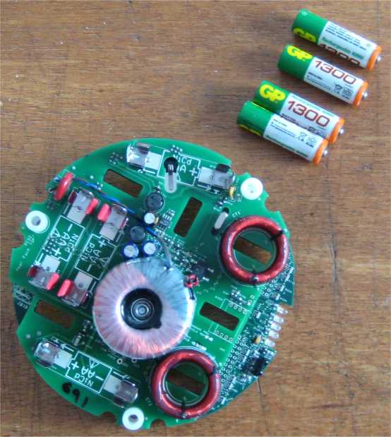
- If replacing the main batteries you will need four AA NiMH GPBatteries GP130AAHC.
- You will be removing the main batteries so any data and user configurations will be lost.
- So download any recording sessions from the Logger using Pronto for Windows.
- Save any user configurations you have created (You do not need to save factory configurations).
You may save your 10 most recently used user configurations into the Logger’s flash memory (which won’t be lost when the batteries are removed) by selecting from the startup screen: CONTINUE – NEXT – CONFIGURE – COPY TO FLASH MEMORY.
If there are more than 10 user configurations then the PmFiles.exe utility can be used to save the rest of the configurations to your computer. This utility is installed to the same directory as Pronto for Windows (see APPNOTE: Utilities installed with Pronto for Windows ).
Removal of the electronics from the enclosure
1. Disconnect the logger from any power source and make sure the charger is not connected.
2. Turn the unit upside-down.

3. Remove the four (or five) split-pins holding the blades in place.
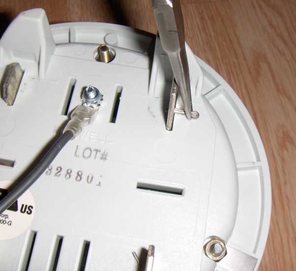
4. Turn the unit top-side up.
5. At the top of the unit identify the 2 (or 3) spade lugs between the blades and the Logger itself.
6. Unplug the spades from the Logger (you may leave them attached to the blades).
7. Remove the blades then identify, loosen and remove the three Phillips head screws. Take care to note the locations of the two contact straps located on back side of the screws at the 4 and 8 o’clock positions. They may stay attached to the bottom of the enclosure or they may pop off. These need to be re-installed in the same locations during re-assembly.
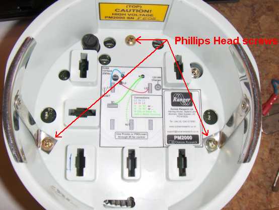
8. Lift off the top half of the enclosure.
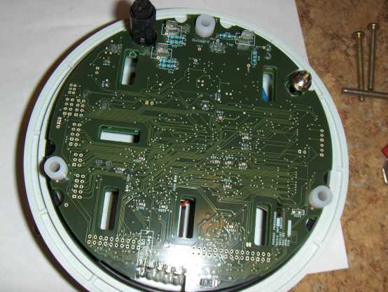
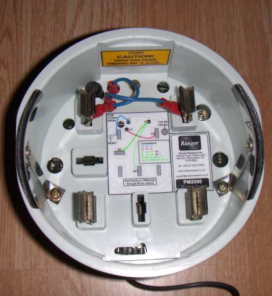
9. Lift out the two board set from the bottom portion of the enclosure. NOTE: there is a wire connection between the PC boards and the bottom of the enclosure so only lift the boards up 4-5 inches and unplug the spade lug from the PC card noting it’s location on JB181 for reattachment later.
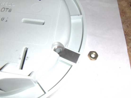
10. If not done at step 7, turn the bottom of the enclosure over and lift off the three nuts and the two contact strips and put them aside.
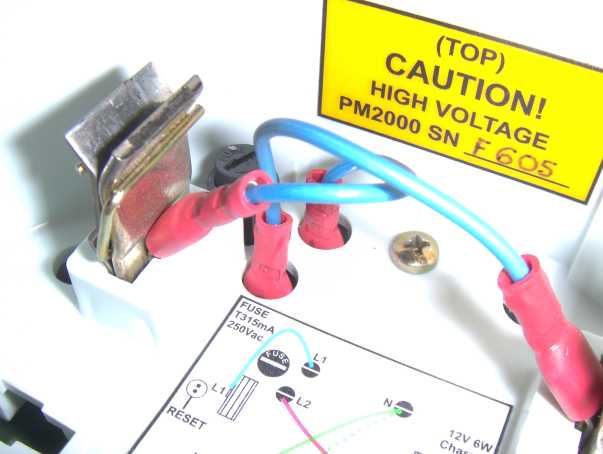
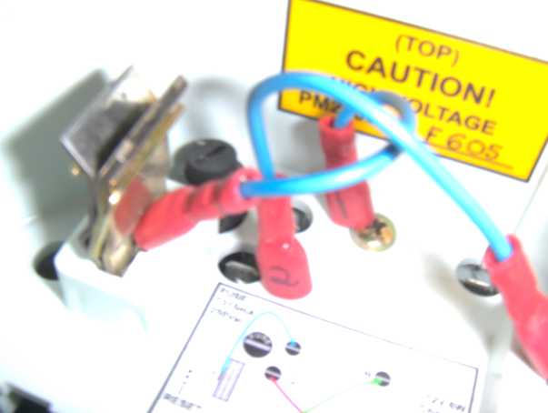
Warning:
Although the battery voltage is low, each battery is capable of storing a large amount of energy. This is not dangerous unless a battery is inadvertently short-circuited. When any such battery is short-circuited a great deal of heat may be generated, especially at the contacts where the short circuit is made and in the conductors where the short circuit current flows. In extreme cases this could result in melting of the insulation or even fire.
To avoid this hazard, after taking the unit out of the box put it down on a dry flat insulating surface that is free from any conducting debris. Take care not to allow the battery contacts to become damaged or to touch any other conductors. Keep the logger well away from any metal objects like scissors or knives or screwdrivers!
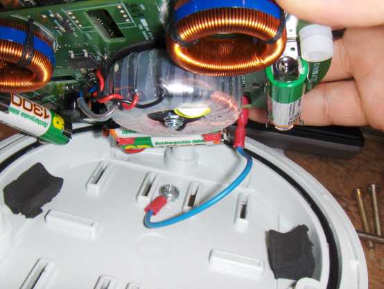
11. Place the board assembly upside down (with the batteries facing up) on a non-conducting surface.
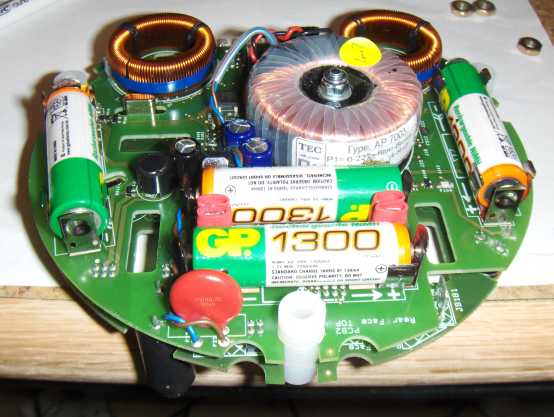
12. Remove the batteries from the power supply board (note that any configurations or recordings present in the logger will be lost at this point).
13. The real time clock battery is located between the two PC cards.
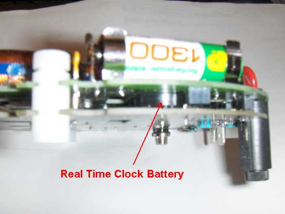
14. To change the real time clock battery the two circuit boards must be separated.
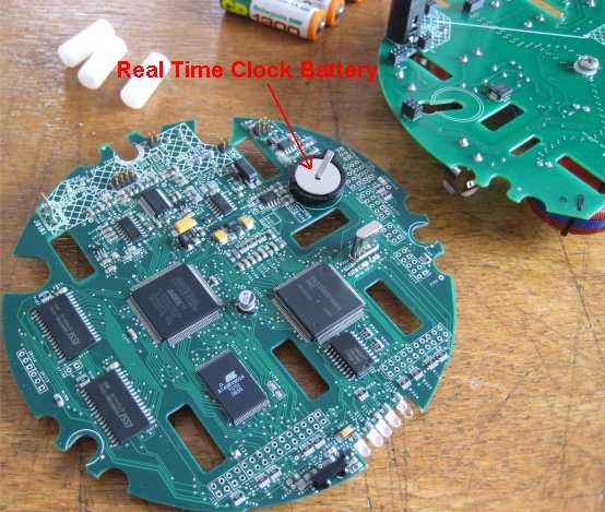
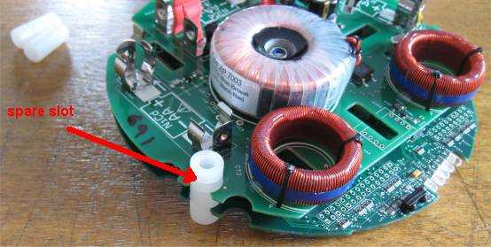
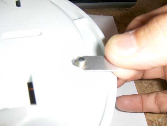
To separate the two PC cards, carefully slide out the three white spacers noting the slots used and the orientation of the spacer. A small screwdriver placed through the hole in the spacer can be used to gain leverage in sliding out the spacers. Also note the connectors that join the two boards. These will need to be re-aligned and seated to re-assemble.
After gently pulling the two boards apart, identify the timekeeper battery and replace it with a new item.
Re-assembly
15. To re-assemble, reverse the procedure.
When rejoining the two boards taking care that the 6-way, 8-way and the two 4-way plugs and sockets are correctly inserted. Fit the white spacers between the boards with the spare slot as shown.
16. Re-attach the wire connection spade lug from the bottom of the enclosure to the spade identified as JB181 on the circuit boards.
Re-inserting the two PC cards back into the bottom of the enclosure making sure the battery clips at the 3 and 9 o’clock positions slide into the enclosure and don’t get caught.
Place the top of the enclosure back over the PC cards and install and tighten the screw at the 12 O’clock position to hold things together. Install the screws at the 4 and 8 o’clock positions and make sure the contact straps as shown are properly located before you fit the nuts.
17. Secure all three screws making sure not to over tighten (15 ft lbs max). Install the 4 blades making sure the two with the spade lugs and wires are at the top, and the wires are facing inward. Reattach the spade lugs as shown on the drawing inside the unit and reinstall the split pins, bending the tabs once they are through the holes.
References
None.