Article ID: 110110jdo
Last Reviewed: July 10, 2023
The information in this article applies to:
- The PM7000 when used to measure the phase between the voltage and current of a particular harmonic. This phase measurement can be useful in determining if the phase is being produced by the attached load or introduced from the power source.
Target Audience
This article is aimed at:
- Users of the PM7000 who wish to measure the phase angle between voltage and current at a particular harmonic.
Summary
Firmware revision 1.095 for the PM7000 adds the option to display and record the phase angle between voltage and current for any of the harmonics measured by the system.
The reason for adding this option is to give greater visibility into the phase (angle) association between voltage and current at any chosen harmonic and for any chosen supply phase. The PM7000 and other PM products provide harmonic direction results based upon this phase relationship, but where significant phase measurement errors exist and where harmonics are present due to both source and load, the result from the decision making process can be given too much weight (ie a firm decision presented may make a marginal situation appear cut and dried, when if fact it is not).
The particular problem arises when the phase angle between voltage and current (for the specific harmonic) is close to +/- 90 degrees. These specific angles are the boundaries for the direction decision. If phase angle is closer to 0 degrees than 180, then the current harmonic is considered to be in phase with voltage, and hence the harmonic is arriving with the source. If phase angle is closer to 180 than to 0 degrees, the voltage harmonic is considered to be responding to current harmonic demand, and hence the load is responsible.
Where phase measurement errors exist – in Secondary CTs, in Voltage output Clamps [1] (and errors tend to increase with higher harmonics), and the where the situation may be confused by both source and load contributing harmonics, possibly compounded by the network characteristics, the actual raw phase angle information is perhaps of greater use than the source/load decision. Accordingly this parameter has now been added to the selection options for the troubleshooting channels in the PM7000.
[1. Provided the processing is carried out properly, Rogowski Coils (being linear devices) should not introduce phase errors in the same way that iron core CTs can.]
Before you start
- You will need a PM7000 with firmware 1.095 or later.
Selection of Harmonic Phase
Starting from the Main Menu:
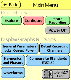
Click on Configure:
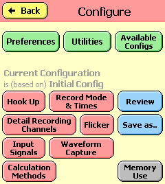
Click on Detail Recording Channels
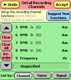
Click on the channel you wish to allocate. You may need to click twice if the channel is not already selected.
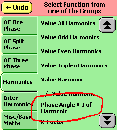
Select the Harmonics function group, then click on the Phase Angle V-I of Harmonic function. This is on the second page. Note that this function will NOT be available if the correspondence between Voltage and Current is not prescribed by the Hook-up (Choice of Hook-up is what tells the logger how current and voltage phase ought to be related. Where the logger is NOT told this e.g. when the Uncommitted Hook-up is in use, it cannot relate the two together, and hence the Harmonic Phase function is not made available). The same criteria apply as for the harmonic direction functions.
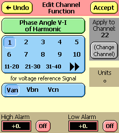
Select the harmonic required and the phase to be examined. Note that for instance “Van” refers to the “A” phase – clearly both Voltage and Current are necessary for the measurement, so “Van” is merely used as the reference for the “A” phase voltage and current combination.
Click Accept then Accept again on the Detail Recording Channels screen then Back out of Configure until the Main Menu is reached.
Display and Recording of result
Phase angle is expressed in degrees in the range +/- 270 degrees. Hysteresis is applied so that wherever the phase lies in the circle, there will be no nuisance switching across a 360/0 or 180/-180 boundary unless the phase actually does rotate repeatedly.
For very small harmonic levels of either voltage or current less than 2 LSBs, the phase cannot be measured, and the result is forced to 0. At levels of 2 LSBs, results will be noisy, becoming more stable the greater the harmonic level.
