Article ID: 060808sab
Last Reviewed: July 5, 2023
The information in the article applies to:
Target Audience
This article is aimed at:
- Advanced users and distributors of the PM7000.
Hook-ups
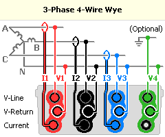 |
3 Phase 4 Wire Wye, use with a three phase star source. Voltage Input V1 is connected between phases A and neutral. Voltage Input V2 is connected between phases B and neutral. Voltage Input V3 is connected between phases C and neutral. Current Input I1 measures the current in phase A. Current Input I2 measures the current in phase B. Current Input I3 measures the current in phase C. This hook up gives correct 3 phase maths function results regardless of any source or load mismatch. The calculated signals Vab, Vbc, Vca are also available. |
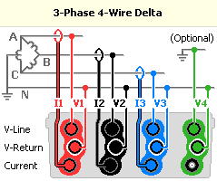 |
3 Phase 4 Wire Delta (high leg), use with a three phase delta source where the center point of one of the phases is earthed and used as a neutral. Voltage Input V1 is connected between phases A and neutral. Voltage Input V2 is connected between phases B and neutral. Voltage Input V3 is connected between phases C and neutral. Current Input I1 measures the current in phase A. Current Input I2 measures the current in phase B. Current Input I3 measures the current in phase C. This hook up gives correct 3 phase maths function results regardless of any source or voltage mismatch. The calculated signals Vab, Vbc, Vca are also available. |
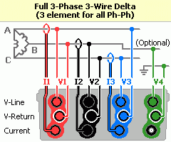 |
3 Phase 3 Wire Delta (3 element), use with a three phase delta source. Voltage Input V1 is connected between phases A and B. Voltage Input V2 is connected between phases B and C. Voltage Input V3 is connected between phases C and A. Current Input I1 measures the current in phase A. Current Input I2 measures the current in phase B. Current Input I3 measures the current in phase C. This hook up gives correct 3 phase maths function results regardless of any source or load mismatch. Calculated RMS between A and E and between C and E are also available.. |
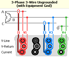 |
3 Phase 3 Wire Wye (with ground), use with a three phase star source. Voltage Input V1 is connected between phases A and B. Voltage Input V2 is not used. Voltage Input V3 is connected between phases C and B. Current Input I1 measures the current in phase A. Current Input I2 is not used. Current Input I3 measures the current in phase C. This hook up gives correct 3 phase maths function results ONLY when there are no other ways for current to flow (vector sum of Ia + Ib + Ic = 0). The calculated signals Vab, Vbc, Vca are also available. |
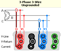 |
3 Phase 3 Wire Wye, use with a three phase star source. Voltage Input V1 is connected between phases A and B. Voltage Input V2 is not used. Voltage Input V3 is connected between phases C and B. Current Input I1 measures the current in phase A. Current Input I2 is not used. Current Input I3 measures the current in phase C. This hook up gives correct 3 phase maths function results ONLY when there are no other ways for current to flow (vector sum of Ia + Ib + Ic = 0). |
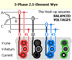 |
3 Phase 2.5 Element Wye, use with a three phase star source. Voltage Input V1 is connected between phase A and neutral. Voltage Input V2 is not used. Voltage Input V3 is connected between phase C and neutral. Current Input I1 measures the current in phase A. Current Input I2 measures the current in phase B. Current Input I3 measures the current in phase C. This hook up gives correct 3 phase maths function results ONLY when the voltages are balanced, i.e. vector sum of (Van + Vbn + Vcn) = 0. |
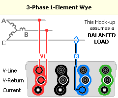 |
3 Phase 1 Element Wye, use with a three phase star source. Voltage Input V1 is connected between phase A and Bl. Voltage Input V2 and V3 are not used. Current Input I1 and I2 are not used. Current Input I3 measures the current in phase C. This hook up gives correct 3 phase maths function results ONLY when voltages and currents are balanced. |
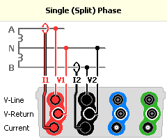 |
2 Phase 2 Element, use with a two phase, split phase source. Voltage Input V1 is connected between phase A and neutral. Voltage Input V2 is connected between phase B and neutral. Voltage Input V3 is not used. Current Input I1 measures the current in phase A. Current Input I2 measures the current in phase B. Current Input I3 is not used. This hook up gives correct 2 phase maths function results regardless of any load or source mismatch between phases. |
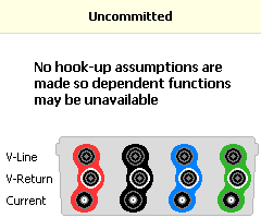 |
Uncommitted, use for non-standard hook ups. No assumptions are made about the hook up. All power maths functions are available. You must ensure measurement functions selected are appropriate for the connections made. Harmonic Direction functions may not be available. |
