Article ID: 120626jdo
Last Reviewed: July 6, 2023
The information in this article applies to:
Target Audience
This article is aimed at:
- All Users of the Ranger Power Master PM3000 with DC Current Measurement Upgrade.
Summary
This application note explains how to set up DC current measurement in the Ranger Power Master PM3000 with the DC Current Measurement Upgrade, using either the touch screen on the PM3000 unit or using PMScreen.
Before you start
You should be using Firmware Rev 2.1xx. As of 27 April 2012, the latest version is 2.126.
The DC functions are available as Maths Functions under Basic Maths 1. They may be used at the same time as normal AC measurement from the same probe.
To use this with the Fluke i310S Hall Effect current probes – Turn current probes on to the 300A range, and connect up, observing the phase identification on the probe labels, and current direction (for the normal AC operation).
To configure the logger to measure the DC
Set logger configuration for the appropriate AC hook-up as normal, e.g. 3 phase 4 wire Wye.
Press on ‘Configure’, ‘Current Config’, ‘Edit’, ‘Input Signals’ and for the Present Current Sensor, choose ‘High Range Voltage o/p (0.5V max)’.
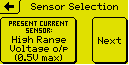
press ‘Next’.
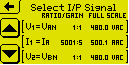
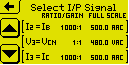
On the Select I/P Signal screen, touch on ‘I1 = IA’. If not already set, set I/P ratio to 1000:1.
Repeat for I2 and I3. All three currents should read Gain = 1000:1, Full Scale = 500.0 Aac.
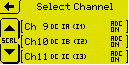
Press back to the ‘Edit Configuration’ screen. Touch on Recording Channels. Scroll down to an “unspecified” channel, and click on it.
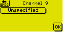
Touch on ‘Unspecified’ and select the ‘Basic Maths 1’ Function Group.
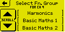
You will see two DC options.
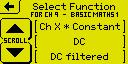
The “DC” by itself measures the DC from each cycle with no carry-over or filtering from previous cycles. The “DC Filtered” takes each cycle’s result and passes it into a simple filter with a 4-cycle Time Constant. In practice the results are not noisy so there is little benefit in using the filter unless you wish to attenuate upwards of 5Hz components.
Choose “DC”.
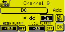
on the channel specification screen, choose the desired input signal (e.g. Ia), and touch ‘OK’.
Choose two more unspecified channels and make them DC for the current on the other two phases.
Return to the Main Menu as normal.
This is all that is required. However a “Zero” function is available to eliminate starting condition offset error from all causes.
To Zero the DC terms.
This function is NOT available during recording. It may only be used in Display mode while NOT recording. Offset data is stored in non-volatile memory and is held across power outages. Each channel must be zeroed individually.
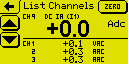
With NO DC passing through the jaws of the probes, from the ‘Main Menu’, select Display, then List Channels.
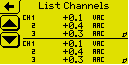
Press anywhere in the top half of the screen to change the three line small display to single line large display.
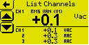
Scroll down to the relevant DC channel.
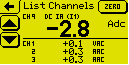
When you get there you will see that a button appears in the top right of the screen labelled “Zero”. This button ONLY appears when the top half of the screen is in Single Line Large mode, and the channel being displayed is a DC type. The button is not present for AC channels, i.e. it is unambiguously available for the displayed DC channel only.
Touch on Zero. The unit will write the offset information into non-volatile storage. When complete, the display screen should return with the offset corrected.
Use the scroll button to go to the next DC channel and zero that. Repeat for the third channel.
Recordings may now be undertaken as normal. Pronto Version 5.67 and later knows about the DC channel option and will display the channel data with the appropriate label.