Article ID: 070615sab
Last Reviewed: July 10, 2023
The information in this article applies to:
Target Audience
This article is aimed at:
- Qualified Service Personnel for the Ranger Product Line.
- These instructions are specifically NOT for untrained end users.
Summary
This application note details the sequence required to change the timekeeper battery in the PM3000.
Before you start
- You will need a replacement timekeeper battery. This is a 3 volt lithium button cell CR1616 or equivalent.
- You will be removing the main batteries so any data and user configurations will be lost.
- So..download any recording sessions from the Logger using Pronto for Windows.
- Save any user configurations you have created (You do not need to save factory configurations).
You may save your 10 most recently used user configurations into the Logger’s flash memory (which won’t be lost when the batteries are removed) by selecting from the startup screen: CONTINUE – NEXT – CONFIGURE – COPY TO FLASH MEMORY.
If there are more than 10 user configurations then the PmFiles.exe utility can be used to save the rest of the configurations to your computer. This utility is installed to the same directory as Pronto for Windows (see APPNOTE: Utilities installed with Pronto for Windows ).
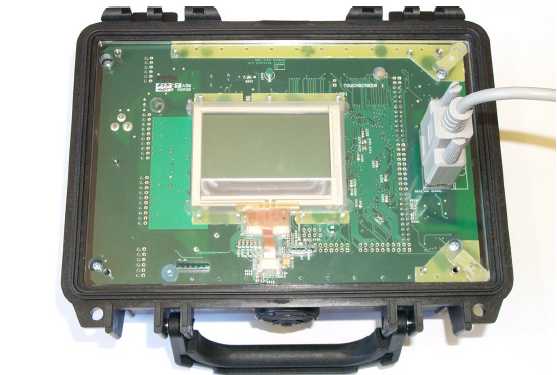
Removal of the logger from the box
1. Disconnect the logger from any power source and make sure no Rogowski coils or voltage probes are attached. Disconnect the RS232 cable if attached but keep it nearby. It is part of the procedure!
2. You will need a small ‘Posidrive’ screwdriver. Unscrew the overlay (four screws, one at each corner). Place it carefully to one side. Now you are looking at the front panel.
3. In the top right and bottom right corners are two locking tongues. Remove their screws. With a sharp pointed implement release the locking tongues from the edge of the box.
4. Now screw your RS232 connector onto its socket in the logger face and use it as a handle to pull the logger out of the box. or turn the box over and gently tap one corner to loosen the logger insides.
The following pictures show the sequence of steps to go through to lift the boards out of the box.
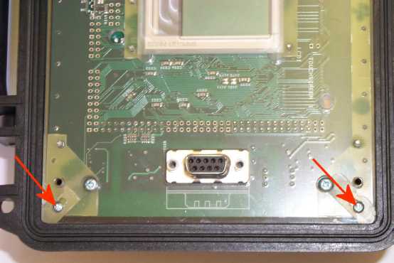
You have removed the overlay and revealed the front panel. Note the two locking tongues and their screws.
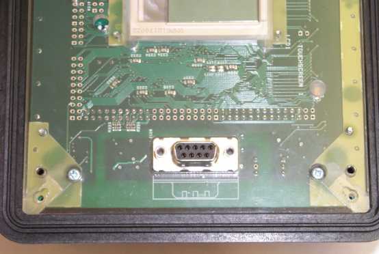
The screws are now removed.
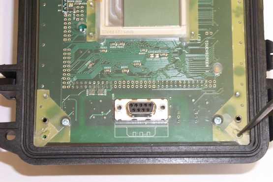
Take your pointed implement and locate it in the top of the locking tongue screw hole, catching the locking tongue,
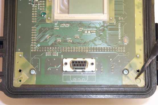
Slide the hole as far as the tongue groove will let you. The locking tongues may be a little stiff the first time they are moved.
When both locking tongues have been released, attach the RS232 cable to its socket.
Use it as a handle to lift the unit out of the box after reading the following precaution!:
Although the battery voltage is low, each battery is capable of storing a large amount of energy. This is not dangerous unless a battery is inadvertently short-circuited. When any such battery is short-circuited a great deal of heat may be generated, especially at the contacts where the short circuit is made and in the conductors where the short circuit current flows. In extreme cases this could result in melting of the insulation or even fire.
To avoid this hazard, after taking the unit out of the box put it down on a dry flat insulating surface that is free from any conducting debris. Take care not to allow the battery contacts to become damaged or to touch any other conductors. Keep the logger well away from any metal objects like scissors or knives or screwdrivers!
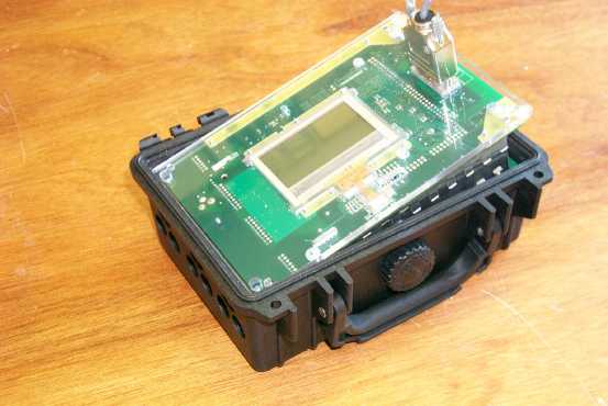
Lift the unit out of the box using the RS232 connector or turn the unit upside down and gently tap the corner of the box to nudge the logger out.
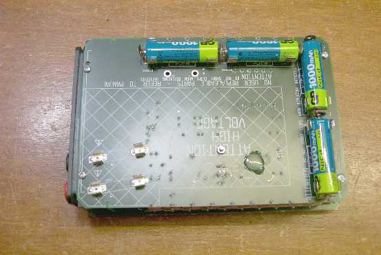
Place the board assembly upside down on a non-conducting surface.
Remove the batteries (note that any configurations or recordings present in the logger will be lost at this point).
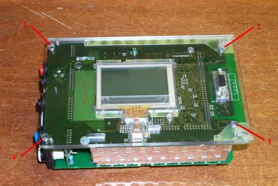
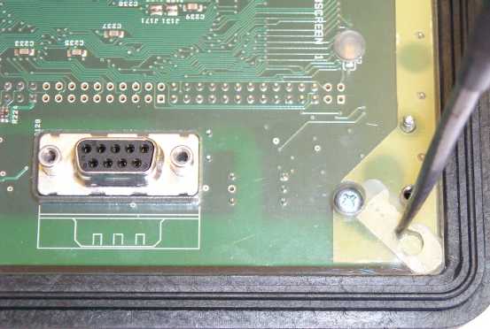
Turn the assembly right side up again and remove the four retaining screws as shown (take care not to push down so hard on the assembly so as to bend the battery clips underneath).
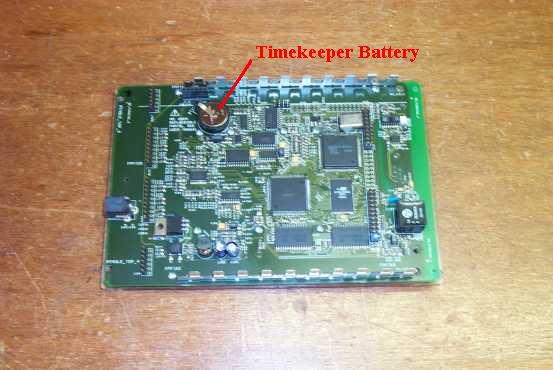
After gently pulling the two boards apart, identify the timekeeper battery and replace it with a new item.
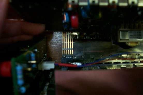
Rejoin the two boards taking care that the 6 way plug is correctly inserted.
The re-assembly process is the reverse of that used for disassembly.
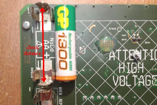
When refitting the main batteries, ensure the battery clips make good contact with the batteries. In particular ensure that the distance between the contacts is less than the 49.2 -> 50.5 mm length of the battery by 3 to 4 mm (about 3/32″). The clips can be bent inwards if required.
References
None.