Article ID: 101104jrl
Last Reviewed: July 10, 2023
The information in this article applies to:
Target Audience
This article is aimed at:
- Qualified Service Personnel for the Ranger Product Line.
- These instructions are specifically NOT for untrained end users.
Summary
This application note details the sequence required to change the battery pack in the PM7000.
Before you start
- You will need a replacement battery pack;
the battery pack is an integrated package comprising thermal protection, internal fuse, welded leads and connector to mate with the PCB; all contained in a heat shrink sleeve. - Recorded data and user configurations may be lost.
Use Pronto for Windows to download any recordings in the Logger.
The PmFiles.exe utility can be used to save configurations to your computer. This utility is installed to the same directory as Pronto for Windows (see APPNOTE: Utilities installed with Pronto for Windows ). - You will need a small ‘Posidrive’ screwdriver, a small flat bladed conventional screwdriver, side cutting micro-shears, replacement cable ties (zip ties).
To separate the PM7000 electronics from the chassis
The battery pack is mounted inside the box just behind the handle, in a polycarbonate shell slid into position behind fixing inserts in the metalwork. The battery pack is accessible after the electronics module is separated from the chassis.
- Disconnect the logger from any power source and make sure no Rogowski coils or voltage probes are attached. Disconnect the USB cable if attached.
- Remove and keep safely the four (4) black 2.5mm corner screws securing the front panel overlay.
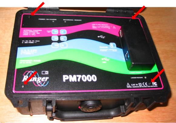
- Remove the overlay. [Note that the overlay may be lightly stuck to the metal front panel plate by double sided tape.
This tape is present purely for cosmetic reasons to hold down the overlay which otherwise can bubble up when warm.
It may be replaced afterwards if desired but it has no electronic significance at all.]You will see nine countersunk screws around the periphery of the front panel and four (4) yellow coverings over the heads of four screws (These four covered screws hold the board sandwich pillars in place and should NOT be undone).
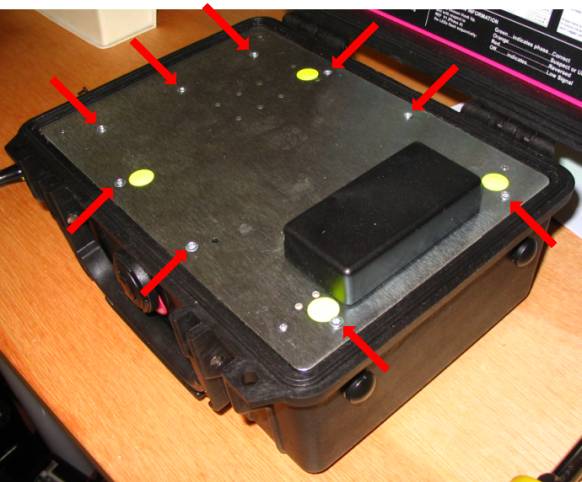
- Remove and keep safely the nine (9) countersunk 2.5mm screws holding down the front panel.
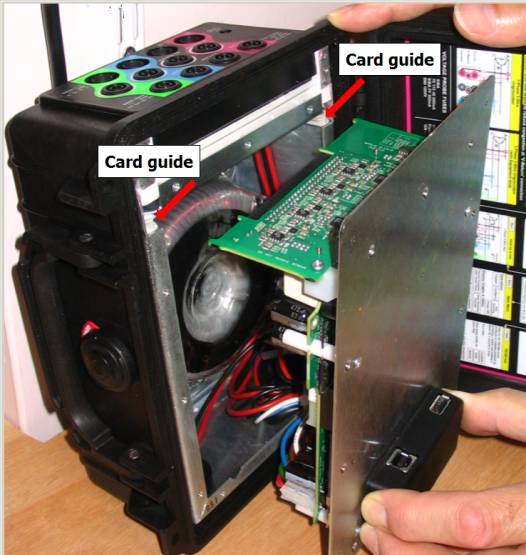
- Stand the unit on end as shown in the picture below. It is helpful to lean the unit against a wall or solidobject as the weight of the metalwork and transformer in the chassis make itprone to fall over.
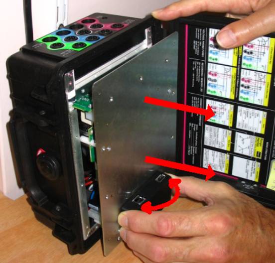
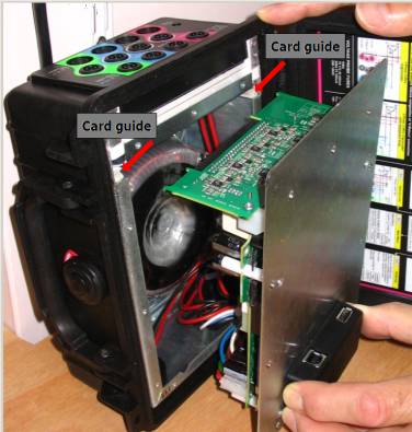
- Holding the black communications housing, twist it gently from side to side (as though trying to twist along the longitudinal axis of the box – first pushing with the thumb and pulling with the fingers, then pushing with the fingers and pulling with the thumb) At the same time pull the whole front panel away from the chassis, Ensure the front panel remains parallel to the chassis even as they separate. The resistance to extraction is from the seating of the analogue PCB in its connector, and the rocking motion will gradually unseat it, allowing you to withdraw it up its card guides and to separate the electronics assembly from the chassis.If the electronics module is not extracted centrally from the chassis you may encounter some sticking at the lower end of the box as the board pillars slide over the metal work. Look for where any catching occurs and ease the panel to the appropriate side to free the obstruction.
Lower the top end of the front panel down to the bench without straining the wiring.
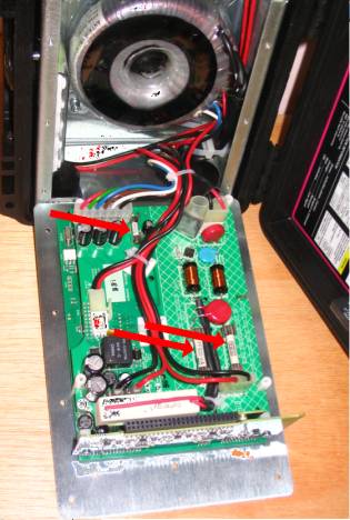
The wiring harness is formed onto the PCB through 3 sticky backed cable tie bases using cable ties. Those three cable ties must be carefully removed leaving the bases undisturbed before the battery pack can be separated from the whole assembly.
Caution
Battery packs may contain considerable stored energy even if almost discharged. This stored energy may be sufficient to melt insulation or induce burning of adjacent flammable objects.
Even though the battery voltage may be low the energy release can be considerable in event of a short circuit. Take care to avoid short circuits and to manipulate the insulated wiring with care.
Leads in the wiring harness carry the full line voltage to the PSU. Make sure all insulation remains undamaged and free from imperfections before returning the unit to service.
Carefully cut the zip ties holding the wires in position and remove them from their bases.
DO NOT CUT THE WIRES OR DAMAGE THE INSULATION – THIS WILL CAUSE THE UNIT TO BE UNSAFE.
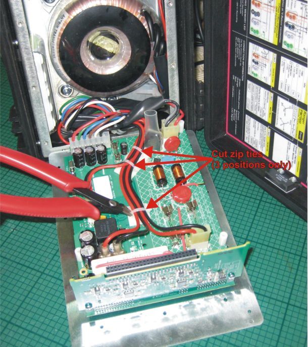
Disconnect the V1 input, Charger Tab Sockets, Transformer Primary, Transformer Secondary & Battery Pack from the Power Supply PCB. (6 connectors disconnected). Take care with the battery connections and avoid short circuits.
Replacing the battery Pack
Description
The battery is supplied as an integrated pack comprising thermal protection, internal fuse, welded leads and connector to mate with the PCB. The pack is mounted using a Polycarbonate shell that slides into position behind the inserts used to fix the front panel in position.
An existing battery pack can be removed by first carefully undoing the nylon retaining screw in the plastic shell; reserve this screw for use when reassembling the unit.
The plastic shell is removed by sliding the battery pack to the left by about 10mm – don’t go too far. A slot in the top lip of the shell allows the pack to be tilted away from the metal case so that the whole thing can then be released from the box.
Some care is required to make sure the slots in the plastic shell clear all of the obstructions around the underside of the metal lip in the top of the box – when the correct position is found the battery pack will easily come clear without needing to apply undue force.
The notes in the following subsections describe fitting a battery pack for the first time, including the fitting of cable clamps. Battery removal is straightforward reversal of this process.
Normally it is not necessary to release the large cable clamp in the corner of the box when removing the battery pack.
Assemble the battery pack into the shell
- First confirm that there is 1mm of neoprene spacer at the bottom of the shell so that the assembly fits snugly.
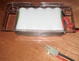
- Confirm that there are no rough edges and that the insulation on the wiring is intact.
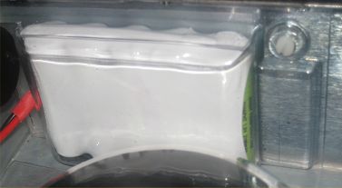
- Confirm that the sleeve over the battery connecting leads pass neatly though the hole in the clear plastic shell – as shown.
- Fit the battery pack into the metalwork and slide along until the screw hole in the plastic lines up with the corresponding nutsert in the metalwork.
- Secure in place using a single M3x6mm NYLON screw (FEC 7070585) at the other end of the pack (NE431).
Confirm HV wiring sits snugly in the Cable Clamp
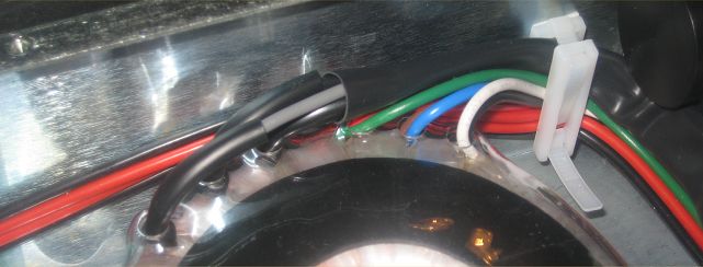
All cables apart from the battery wires are routed through the RHS cable clamp. These should not need to be disturbed when replacing a battery but the routing is shown below for completeness.
Confirm that the mains and charger cables pass neatly between the transformer case and the sidewall, passing through to the clamp to lie flat along the box wall like a ribbon cable.
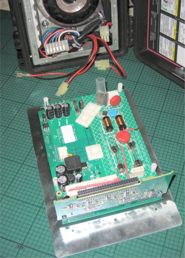
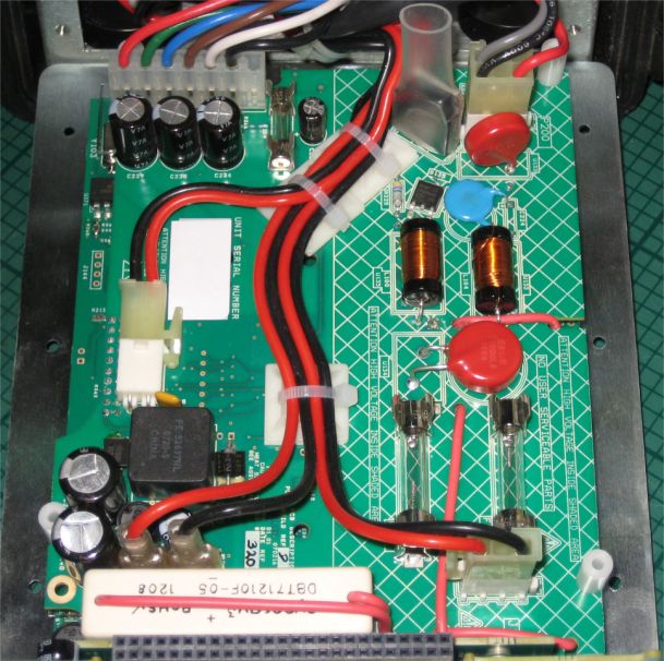
Routing the wires along the PCB
The wiring harness is formed onto the PCB through 3 sticky backed cable tie bases using cable ties. The connections must now be remade and the wires carefully reattached using new cable ties as illustrated below.
Arrange the Board set below the box on its end as before (support the box to stop it falling) and remake all the wire connections. (6 connectors)
Fit 3 new zip ties to keep the wires in position, the wires must be kept as flat as possible to clear the top of the transformer in the box when the unit is reassembled.
Cut the ends of the zip ties short, visually confirm the integrity of all insulation and then follow the notes on “Replacing the electronics module”
Replacing the electronics module
The reverse process is somewhat simpler because it is easier to push the analogue PCB home than to extract it.
Carefully raise the open end of the electronics/front panel assembly and offer the perpendicular analogue board into its card guides.
Ensure the wiring tucks neatly down into the gap beside the transformer. (If the temperature is very cold, the wires may be stiff and unbending. Take the unit into a warmer environment where the insulation will become softer and more pliable.)
Once the analogue board is about to engage it may be easier to lay the unit on its base again.
Keeping the front panel parallel with the chassis lip, lower the analogue board down its card guide, easing the other end of the module past the lip of the chassis. Do not force. The front panel will slide into place but you will be compressing the wiring into its normal position so expect a little resistance from the lower (right hand) end, and a little resistance from the left hand end as the analogue board connector mates.
Inserting front panel screws
Caution: The fitting sequence is best done as described below. If you choose a different sequence you may find you have difficulty in lining all the holes up. Ensure you use the correct screwdriver. Using a worn screwdriver or the wrong size may damage the screw heads.
It is a good idea to fit the four overlay screws loosely into position before tightening up the front panel countersunk screws. This way the holes in the front panel and the chassis behind will automatically be aligned to take the black screws when the overlay is fitted.
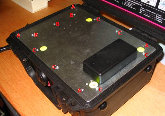
Sequence
Loosely fit three (3) screws down the left hand strip (B). These attach to the vertical metal plate underneath which has a high degree of compliance and needs these screws for its final location. You may find that you need to line the front panel up on these screw holes and fit the screws before attempting to line up the front panel on the other holes.
Fit the four (4) black overlay screws loosely into their corner positions (A). Loosely fit the remaining six (6) screws into their respective holes (C).
Tighten the nine (9) countersunk screws (B), (C). Without removing them, ensure the four (4) black overlay screws (A) can be screwed up and down in their holes easily. [If any are particularly stiff, ease off the countersunk screws (B), (C). Screw down the overlay screws (A) tight. Re-tighten countersunk screws (B), (C) and try again.]
Finally remove the four (4) black overlay screws (A), and fit the overlay, adding double sided adhesive tape in the centre if desired. Replace and tighten the four (4) black overlay screws.
References
None.