Article ID: 080313jdo
Last Reviewed: July 10, 2023
The information in this article applies to:
Target Audience
This article is aimed at:
- Qualified Service Personnel for the Ranger Product Line.
- These instructions are specifically NOT for untrained end users.
Summary
This application note details the sequence required to change the fuses in the PM7000.
These fuses are in Phase A voltage inputs and protect the power supply.
Before you start
- Read and understand the section on Intended Use and Safety in the PM7000 User Manual.
- You will need some replacement fuses,
There are three replaceable fuses in the PM7000:
– Two Bussmann 150mA 1000V Time Delay (part number TDC11-150mA) and
– One Littelfuse 213 series 250V Slow Blow,
either:
315mA part number Littelfuse 0213.315MXP (serial numbers 1285 and lower).
or
400mA part number Littelfuse 0213.400MXP (serial numbers 1286 and higher). - Recorded data and user configurations may be lost.
Use Pronto for Windows to download any recordings in the Logger.
The PmFiles.exe utility can be used to save configurations to your computer. This utility is installed to the same directory as Pronto for Windows (see APPNOTE: Utilities installed with Pronto for Windows ). - You will need a small ‘Posidrive’ screwdriver.
To separate the PM7000 electronics from the chassis
The fuses are mounted on the underside of the Power Supply circuit board. They are accessible after the electronics module is separated from the chassis.
- Disconnect the logger from any power source and make sure no Rogowski coils or voltage probes are attached. Disconnect the USB cable if attached.
- Remove and keep safely the four (4) black 3mm corner screws securing the front panel overlay (early Loggers used 2.5mm screws).
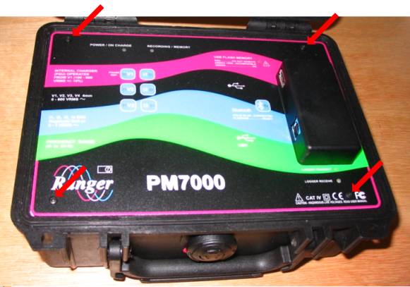
- Remove the overlay. [Note that the overlay may be lightly stuck to the metal front panel plate by double sided tape.
This tape is present purely for cosmetic reasons to hold down the overlay which otherwise can bubble up when warm.
It may be replaced afterwards if desired but it has no electronic significance at all.] You will see nine countersunk screws around the periphery of the front panel and four (4) yellow coverings over the heads of four screws (These four covered screws hold the board sandwich pillars in place and should NOT be undone).
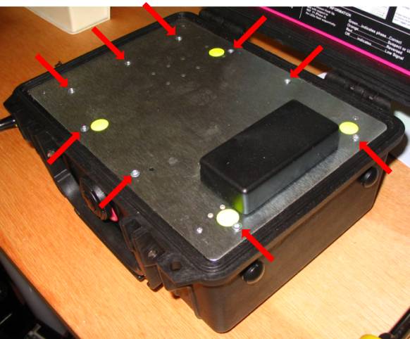
- Remove and keep safely the nine (9) countersunk 3mm screws holding down the front panel.
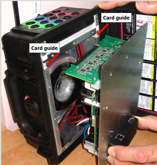
- Stand the unit on end as shown in the picture below. It is helpful to lean the unit against a wall or solid object as the weight of the metalwork and transformer in the chassis make it prone to fall over.
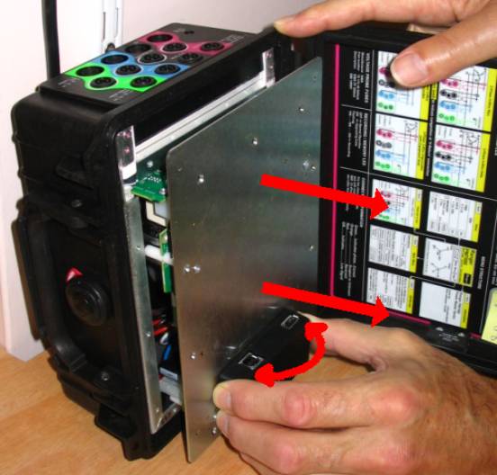
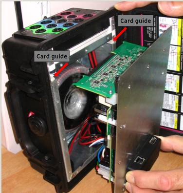
- Holding the black communications housing, twist it gently from side to side (as though trying to twist along the longitudinal axis of the box – first pushing with the thumb and pulling with the fingers, then pushing with the fingers and pulling with the thumb). At the same time pull the whole front panel away from the chassis, Ensure the front panel remains parallel to the chassis even as they separate. The resistance to extraction is from the seating of the analogue PCB in its connector, and the rocking motion will gradually unseat it, allowing you to withdraw it up its card guides and to separate the electronics assembly from the chassis.If the electronics module is not extracted centrally from the chassis you may encounter some sticking at the lower end of the box as the board pillars slide over the metal work. Look for where any catching occurs and ease the panel to the appropriate side to free the obstruction.
Lower the top end of the front panel down to the bench without straining the wiring.
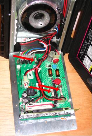
The fuses are now visible and may be removed by gently rising them out of their clips with a small screwdriver. Take care not to scratch or damage the circuit board.
Checks to perform before replacing the Electronics module
- Inspect the circular red MOVAR U134 (lying flat on the circuit board) to ensure its connections are not damaged.
Replacing the electronics module
The reverse process is somewhat simpler because it is easier to push the analogue PCB home than to extract it.
Carefully raise the open end of the electronics/front panel assembly and offer the perpendicular analogue board into its card guides.
Ensure the wiring tucks neatly down into the gap beside the transformer. (If the temperature is very cold, the wires may be stiff and unbending. Take the unit into a warmer environment where the insulation will become softer and more pliable.)
Once the analogue board is about to engage it may be easier to lay the unit on its base again.
Keeping the front panel parallel with the chassis lip, lower the analogue board down its card guide, easing the other end of the module past the lip of the chassis. Do not force. The front panel will slide into place but you will be compressing the wiring into its normal position so expect a little resistance from the lower (right hand) end, and a little resistance from the left hand end as the analogue board connector mates.
Inserting front panel screws
Caution: The fitting sequence is best done as described below. If you choose a different sequence you may find you have difficulty in lining all the holes up. Ensure you use the correct screwdriver. Using a worn screwdriver or the wrong size may damage the screw heads.
It is a good idea to fit the four overlay screws loosely into position before tightening up the front panel countersunk screws. This way the holes in the front panel and the chassis behind will automatically be aligned to take the black screws when the overlay is fitted.
Sequence
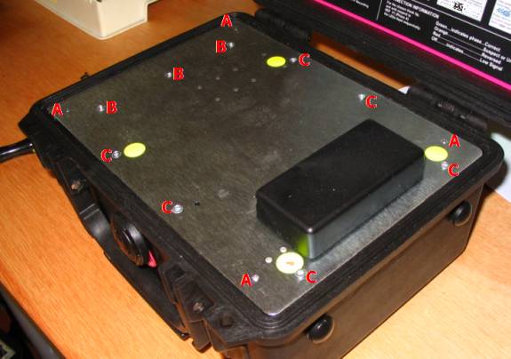
Loosely fit three (3) screws down the left hand strip (B). These attach to the vertical metal plate underneath which has a high degree of compliance and needs these screws for its final location. You may find that you need to line the front panel up on these screw holes and fit the screws before attempting to line up the front panel on the other holes.
Fit the four (4) black overlay screws loosely into their corner positions (A). Loosely fit the remaining six (6) screws into their respective holes (C).
Tighten the nine (9) countersunk screws (B), (C). Without removing them, ensure the four (4) black overlay screws (A) can be screwed up and down in their holes easily. [If any are particularly stiff, ease off the countersunk screws (B), (C). Screw down the overlay screws (A) tight. Re-tighten countersunk screws (B), (C) and try again.]
Finally remove the four (4) black overlay screws (A), and fit the overlay, adding double sided adhesive tape in the centre if desired. Replace and tighten the four (4) black overlay screws.
References
None.